MeltCam Melt Pool Sensing

Every defect starts in the melt pool.
Why aren't you monitoring it?

Most metal AM builds run on a fixed recipe using laser power, scan speed, and other parameters, and a good build is assumed if the recipe ran correctly. When the process is monitored, it's often with sensors watching the whole build plate for anomalies, not always thermal in nature, and not a calibrated, spatially resolved read of the melt pool itself. Porosity, lack of fusion, and keyholing are decided there, in milliseconds, long before CT scanning or cross-sectioning finds out. MeltCam™ provides real-time, spatially resolved thermal imaging and metrics for the one thing that actually determines whether the part is good.
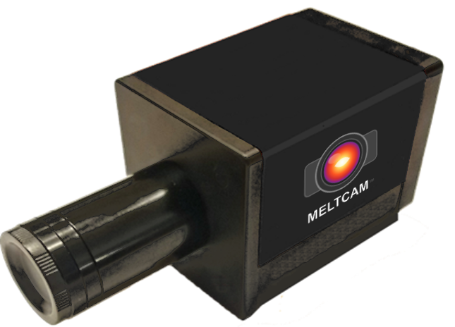
MeltCam sensor
MeltCam™ Sensor
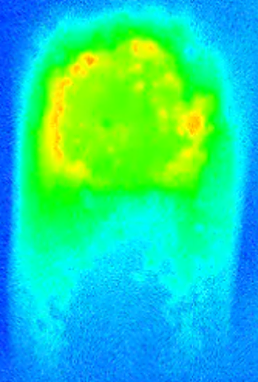
MeltCam melt pool thermal image 2333 °C 2166 °C 1999 °C 1832 °C
Melt Pool Imaged With MeltCam™

The Case For In-Situ Melt Pool Temperature Monitoring

Porosity, lack of fusion, and keyholing are decided in milliseconds, inside a pool a few hundred microns across. Post-build CT and cross-sectioning tell you a defect happened. Only real-time, spatially resolved thermal imaging and metrics can tell you while there's still time to correct the process, part by part, layer by layer, not just batch by batch.

01

Defects form in microseconds

Keyholing and lack of fusion are governed by melt pool geometry and peak temperature at the moment of exposure. By the time a part is off the machine, the evidence is buried in the microstructure, not the process log.

02

Post-process inspection doesn't scale

CT scanning every part, every build, isn't a production strategy for defense and aerospace volumes. In-process thermal monitoring is the only approach that scales to part-by-part qualification instead of statistical sampling.

03

Closed-loop control needs a real signal

You can't correct what you can't measure. Adaptive process control, adjusting power or speed in response to the actual melt pool, requires a trustworthy, spatially resolved temperature field, not a single point, not after the fact.

The Cost Of An Unmonitored Melt Pool

Finding out that your part has to be scrapped at the end is backwards.

Take the typical costs for an Inconel 718 build as an example.

Machine Time + Powder
(60-Hour Inconel 718 Build)
$1,500–$6,000
Amortized machine rate plus powder consumed, before labor
Fully Loaded Cost
(Incl. Heat Treat, HIP, Machining)
$2,000–$12,000+
Inconel 718 carries an above-average post-processing burden
CT / NDE Inspection
$150–$600
Per part, the step that finally reveals whether the build was good

Every one of those costs is sequential and cumulative. Machine time and powder are spent first, during the build. Heat treatment, HIP, and machining happen after, on a part that's only worth finishing if it's actually sound. A defect caused by a bad temperature reading at hour 5 of a 60-hour build isn't discovered until final inspection, plus however many days of post-processing came before it. Every dollar spent in between is money spent finishing a part that was already going to be scrapped.

MeltCam™ doesn't compete with NDE, it's what determines whether the CT scan confirms a good part or discovers an expensive mistake. In-process monitoring is the only intervention that happens before the cost is fully committed, not after.

Your Camera Reports In Celsius. It Only Looks Like Temperature.

Why Most Ways Of Measuring It Fall Short

To compute temperature, many melt pool sensors assume an emissivity value. That assumption drifts with material, surface condition, and the solid-to-liquid transition itself. Two-Wavelength pyrometry can cancel emissivity out mathematically. But imaging two wavelengths through real lenses suffers from aberration and you lose the clean thermal image you were trying to get in the first place. MeltCam™ handles both. Get that assumption wrong and the instrument can under-read the temperature of the molten metal by hundreds of degrees, and if you believe the pool hasn't reached melting temperature when it already has, the natural response is to add power, pushing the real pool further into the superheat that causes keyholing.

A

Material to material

Tool steel, stainless, Inconel 718, Ti-6Al-4V, and CuNi each radiate differently at the same true temperature. A camera tuned for one alloy is systematically wrong on the next one, unless it's re-calibrated by hand every time the material changes.

B

Solid to liquid

The bigger jump isn't between alloys, it's the phase change itself. Surface emissivity shifts as the pool goes from oxidized, textured solid to smooth reflective liquid. That's exactly the moment process control needs the reading most.

C

IR Doesn't Fix It

Moving to infrared doesn't fix the assumption. NIR and SWIR behave like visible light, same math, same failure mode. LWIR trades a gentler emissivity-error curve for lower absolute emissivity in metals, plus detector saturation against melt pool temperatures and optics that drift with heat. Different problems, not fewer.

D

Two-Wavelength Pyrometry Almost Gets You There

Two-Wavelength pyrometry cancels emissivity out mathematically. But imaging two wavelengths through real lenses suffers from aberration and you lose the clean thermal image you were trying to get in the first place.

Four ways people image melt pools today. Only one holds up across a real build.

Every alternative approach makes a trade you don't have to.

EO / ND

Intensity-Only Imaging

An electro-optical camera with a neutral-density filter, watching brightness, not temperature. No emissivity correction is even attempted, so a hotter pool and a shinier pool produce the same signal. Good for gross fault detection, blind to the difference between a thermal event and a surface change.

Single-Wavelength Pyrometry

Converts brightness to temperature using an assumed emissivity. Accurate only as long as that assumption holds, and it doesn't, across materials, across the solid-liquid transition, or across a build with any surface variation at all. Every reading carries an unmeasured, unbounded error.

Two-Wavelength Pyrometers

Gets the ratio physics right, but is vulnerable to the same two-wavelength aberration MeltCam™ corrects for. Uncompensated, that produces blurry fields and inaccurate profiles, good for point detection, inadequate for measuring melt-pool geometry, keyholing risk, or defect location.

MeltCam™

Optimized Two-Wavelength Imaging

Ratio-based measurement like the best two-wavelength pyrometers, corrected for two-wavelength aberration, and imaged across the full melt pool like a camera. You get a temperature field, not a single number, with the emissivity problem already cancelled out.

MeltCam™ Two-Wavelength Approach

MeltCam™ combines the sound physics of the two-wavelength approach with a proprietary, physics-based correction that mitigates two-wavelength aberration.

Emissivity term cancels. Aberration is corrected. What's left tracks true temperature.

See MeltCam™ In Action

Same Melt Pool. Same Instant. Two Very Different Pictures.

A single layer from a three-laser Ti-6Al-4V LPBF build, lasers running in lead-chase formation, imaged two ways at once.

Electro-Optical Camera

Bright, saturated blobs. No temperature information, no way to tell a hot pool from a bright one.

MeltCam™

Same instant, same lasers. A calibrated, spatially resolved temperature field for every pool, in real time.

> 3000 ⁰C~ 100 µm
What This Frame Caught

Peak Temperature Over 3,000°C. Lasers Misaligned By About 100 Microns.

This is a single MeltCam™ frame from the same multi-laser build, both measurable directly in the MeltCam™ GUI, not inferred after the fact. The lead laser is running well above target temperature, and the trailing lasers have drifted out of their intended lead-chase spacing by roughly 100 µm. Neither of these is visible in an intensity-only image. Both are exactly the kind of fault a two-color spot pyrometer would miss entirely, since it reads one point, not a field, and exactly what a single-wavelength reading would misreport, since it can't be trusted at all once the pool is this far into superheat.

Works across processes, not just one. The same MeltCam™ imaging shown here on LPBF has also been demonstrated on powder and wire DED builds, same emissivity-cancelling, aberration-corrected physics, a different deposition process entirely.

The MeltCam™ GUI

A Temperature Image Is The Starting Point, Not The Deliverable.

The GUI ships with a plug-in architecture: images flow into user-defined Metrics Plug-Ins (DLLs you write), and the resulting metrics flow out through user-defined Export Plug-Ins, whether that's logging, integration with your own process control, or a custom pipeline entirely. You're not locked into the metrics and export capabilities MeltCam™ ships with.

Metrics/CommandsUser Defined Export Plug-InsImagesUser Defined Metrics Plug-InsMetrics

Images flow through user-defined Metrics Plug-Ins; the resulting metrics and commands flow out through user-defined Export Plug-Ins, straight to your own control or logging pipeline.

Software Plug-Ins That Ship By Default

The default Metrics Plug-In computes, per frame, in real-world build units (microns and/or mm) from spatial calibration, not pixels:

Max Temperature
Max Temperature Location (x, y)
Average Melt Pool Temperature
Melt Pool Length
Melt Pool Width
Melt Pool Area (µm²)
Bounding Box Corner Points (4)
Bisecting Line End Points (2)

The default Export Plug-In streams the metrics from the default metrics plug-in via UDP/IP to an IP address and port you select.

Specifications

What's Actually In The Box

Targets and demonstrated performance for the current MeltCam™ system.

Measurement
Measurable Temperatures
Targeting 700°C – 3,100°C or better
Frame Dynamic Range
Targeting 2,000°C or better
Compatible Materials
Demonstrated on copper-nickel, steel, titanium, Inconel, and their family of alloys. Other materials possible with potential constraints.
Camera
Size
Approx. 2.5″ × 2.5″ × 3.5″ (excl. connectors and lens tube)
Weight
Approx. 0.6 lb (without lens / lens tubes)
Typical Installation Resolution
10–30 µm/pixel
At 20 µm/Pixel
160 × 160 px @ 3.2 mm FOV · 400 × 400 px @ 8.0 mm FOV
Maximum Image Size
1440 × 1080
Frame Rate
1000 FPS @ 80×80 px · 540 FPS @ 160×160 px · 100 FPS @ 400×400 px
Optical Interface
C-Mount lens. Optical path requires reasonable response between 700–950 nm. Specific filtering selected during calibration.
Operating Environment
23°F to 113°F, 20–80% non-condensing humidity
Storage Environment
–13°F to 140°F, 20–80% non-condensing humidity
Built Across Alloys

One sensor, no re-calibration between materials.

MeltCam™ has been run across the alloy systems that matter most in defense and aerospace additive manufacturing.

Tool Steel
validated
Stainless Steel
validated
Inconel 718
validated
Ti-6Al-4V
validated
Cu-Ni
validated
Pricing & How To Buy

One sensor per machine. One calibration kit for your whole floor.

Each machine needs its own MeltCam™ sensor. One calibration kit travels with you across every machine you own.

Per Machine

MeltCam™ Sensor

$20,000/ unit
  • Camera + power supply
  • Basic lens tube, lens, filters
  • 10 GbE PCIe v3.0 card
  • Windows 11 MeltCam™ software
  • Basic image acquisition
  • Basic metrics
  • Basic export
  • Basic sensor command/control
  • Basic image viewing software
Buying more than one? Volume pricing is available, so contact us below.
Shared Across Machines

MeltCam™ Calibration Kit

$5,000/ unit
  • Thermal calibration fixture
  • Spatial calibration fixture
  • Thermal/spatial fixture power supply
  • Windows 11 MeltCam™ calibration software
One kit is typically all a multi-machine shop needs.
Get In Touch

Talk To Us About Your Process

Tell us about your setup, and we'll follow-up with you directly.